
How can I print?
WinFIG does not have a built-in printing. You have to export your drawing to someprintable format. You can export to PDF, PostScript, LaTeX…
It mostly depends on whether you are using LaTeX formatted texxt objects. If you are not using LaTeX, you can simply export to PDF and print your PDF. You need GhostScript on your computer.
If you are using LaTeX then you can actrivate the check box “Use LaTeX for rendering LaTeX formatted texts” in the PDF/PS/EPS export. For that you need GhostScript and LaTeX on your computer.
You can also export using pstex or pdftex and include the exported files in your own LaTeX document and print that.
How can I combine WinFIG and LaTeX?
There are several ways. The most recommended are either using PSTeX or PSTricks export.
How can I include LaTeX formula?
If you create text objects in WinFIG for LaTeX formula you have to take care of the “LaTeX” flag. That is a button in the tool bar visible on the right, when the text tool is activated.
If the LaTeX flag is not set, some characters are escaped e.g. "$ just_a_test" is exported as "\$ just\_a\_test", which is suitable for LaTeX text to output the special characters correctly, but if you want to enter a formula, the $ and some other characters must not be escaped. So, set the LaTeX flag for a formula.
The LaTeX flag prevents characters like _ or $ from being escaped. You can then enter formula the same way as in a LaTeX document e.g. $(x_i)^2$ will create a formula with a subscript i and a superscript 2 when you create the dvi-file from the LaTeX file.
How can I create a LaTeX file with PSTeX or PDFTeX?
You can mix PostScript an LaTeX with the PSTeX or PDFTeX export. The following explains the necessary steps for PSTeX, but it applies similarly to PDFTeX.
The PSTex export creates two files out of one FIG file, one with the suffix pstex_t and one with the suffix ps (or pdftex_t and pdf for PDFTeX export).
Example: If you have a file foo.fig, you get the files foo.pstex_t and foo.ps where the PS file contains PostScript code for the graphics part while the pstex_t file contains LaTeX code for the text objects (those with the “LaTeX” flag set). The pstex_t file also contains an include directive for the PostScript file like that:
\begin{picture}(0,0)%
 \includegraphics{foo.ps}%
 \end{picture}%
You still have to reference the pstex_t file within your LaTeX document. A minimal LaTeX file could like like this:
\documentclass[11pt]{article}
\usepackage{color}
\usepackage{graphicx}
\begin{document}

\input{foo.pstex_t}

\end{document}
Then use a LaTeX processor to convert that file to DVI (or pdflatex for PDF). The processor will also take care of the included PostScript (or PDF) graphics. So, the document structure is like that: maindocument.tex references foo.pstex_t references foo.eps.
You will find more explanations and examples here: Using Xfig and LaTeX together
My exported PostScript or PDF files don’t contain LaTeX formatted texts.
The PS and PDF export do not apply LaTeX processing. That’s why the LaTeX texts appear with raw LaTeX syntax. To obtain PS or PDF files with LaTeX formatting you need to use the pstex or pdftex export, import the resulting pstex_t (or pdftex_t) file into a main LaTeX document and run the main document through latex (and dvips) or pdflatex. WinFIG contains a convenience function that creates the main document on the fly and executes all necessary steps.
For PostScript:Choose PostScript export and set the checkbox “Use LaTeX for rendering LaTeX formatted texts”.
For EPS:Choose EPS export and set the checkbox “Use LaTeX for rendering LaTeX formatted texts”.
For PDF:Choose PDF export and set the checkbox “Use LaTeX for rendering LaTeX formatted texts”. If you want the output to be cropped to its content, see the question below.
You can edit the temporary main document by clicking on the button “Edit TeX envelope”.
How can I export to PDF, but crop the output to the content?
Edit the TeX envelope and set the “standalone” document class. Also remove the declaration of the gemoetry package. This is a working example:
\documentclass[tightpage]{standalone}
\usepackage{color}
\usepackage[latin1]{inputenc}
\usepackage{graphicx}
\usepackage{mathrsfs}
\thispagestyle{empty}

\begin{document}

\input{"INPUTTEXFILETOKEN"}

\end{document}
I was unable to export any files from WinFIG.
Check if you dragged the WinFIG.exe on your desktop. In that case WinFIG is not anymore in the same folder like fig2dev.exe, which is called when exporting a file. If that is the case, put WinFIG.exe back in its folder and create a shortcut instead. There is a help topic in the Windows help named “Put a shortcut on the desktop”.
My exported files are empty and have 0 size.
Some formats require a GhostScript installation (PDF and all bitmap formats except GIF). You get GhostScript here. GIF requires ppmquant, which you can get as part of the netpbm package.
I tried to install WinFIG onto one of my machines, and put in the registration through “help” button and was given an error saying — Licence key confirmed, but the key could not be written to
This probably occurs on Windows 7 or 8 installations. WinFIG could not write the keyfile due to lack of permissions. You have to run WinFIG with administrator privileges.
- Right-click the program icon or shortcut, and then click “Run as administrator”.
- Or press and hold Ctrl+Shift while opening the program.
When exporting via fig2dev I get an error dialog reporting “error code 2”
fig2dev was not found. Check the previous item. If that didn’t help, add the WinFIG folder to the path environment variable If that does not work or if you do not get an error dialog, try calling fig2dev with the same parameters from the command prompt e.g. fig2dev -L ps infile.fig outfile.ps
Drawings that were created with Xfig using metric units (cm) are slightly smaller in WinFIG.
FIG drawings store coordinates based on 1200 dpi. The input device (the screen) is naturally using a smaller resolution i.e. 80 dpi. Therefore WinFIG/Xfig must convert mouse clicks from the display resolution to the higher file resolution. Xfig uses different display resolutions depending on the unit that is being used. If the figure is using imperial (Inches), the input device is assumed to have fixed 80 dpi.
If the figure is using metric units, the input device is assumed to have 76.2 dpi, but the translation into 1200 dpi is the same for both.
Example: If you draw a 4cm long line using Inches you get p1(0, 0) p2(1890, 0):
4cm == 1.575in == 1890pixels at 1200 dpi
When you draw the same line using metric unit, the line extends from p1(0, 0) to p2(1800, 0), which is not correct. The second coordinate is by the factor 80/76,2 smaller: 1890 / (80/76,2) = 1800. SO, Xfig creates different coordinates for the same figure depending on whether you have set the units to Imperial or Metric. I think this is a bug, because your screen does not change when you change the units.
What happens when you export such a figure to for instance PDF? With those different coordinates in a 1200 dpi resolution Xfig would create lines of different length on paper. Xfig corrects that by scaling the coordinates. When Xfig displays or exports metric figures it scales up by the factor 80/76.2 = 1.0499 to get correct coordinates.
I had to make a decision whether use the same incorrect logic or use the same resolution for Imperial and Metric. I chose the latter. WinFIG allows users to work with different resolutions: 72 dpi, 80 dpi or the physical screen resolution obtained from the graphics driver (i.e. 96 dpi). The latter ensures that 1 cm is really 1 cm on your screen too.
WinFIG produces correct and identical coordinates for both units. Therefore my Windows version of fig2dev does not multiply metric coordinates with 1.0499. If you want to use it for converting Xfig created metric drawings you have to use the option -m 1.0499.
There are some consequences for interchangeability.
Exchanging files between Xfig and WinFIG:
- No problem with drawings using imperial units
- Xfig created metric drawings must be scaled up by 1.0499 to get the correct size in WinFIG. It is easier to save from Xfig using imperial units.
- If saving from WinFIG using Metric units you may edit the FIG file and replace Metric by Imperial (in the 4th line) before loading the file into Xfig. This will prevent Xfig from scaling the figure by 80/76,2
Using fig2dev on Windows to convert figures:
- No problem with drawings using imperial units
- Xfig created metric drawings must be scaled up using “-m 1.0499”
- No problem with WinFIG created metric drawings
You can avoid all that trouble by using imperial units only.
I cannot export figures containing 24 bit PNG images to PostScript.
fig2dev uses the CImage class for reading PNG and GIF files. That class has a bug when reading 24 bit PNG images. It converts to 8 bit, but does not provide the color map, therefore those images cannot be read. Use JPEG instead.
fig2dev does not create GIF files
fig2dev creates by first creating PPM and converting this to GIF using a tool called ppmtogif. I did not check whether ppmtogif is available for Windows. If so, you have to install it, if not, try creating PNG. It is a much better format anyway.
I’m exporting to EPS using the option “Relative to screen (upper left corner)” with values in (X0, Y0) and (Wx, Wy), but it produces strange results.
I’m not sure that fig2dev implements this feature correctly. It seems X0 refers to the upper left edge of the screen, but Y0 refers to the upper bound of the figure. Try using thw “Relative to figure (lower left corner)” option.
How can I include EPS files in LaTeX?
There are several ways to do this, e.g. use the graphicx package. See http://www.math.nwu.edu/comp-help/including_graphics.html
How can I edit text objects?
You can edit text by selecting the text object, so that the markers turn red and then clicking on the button “Edit…” in the toolbar on the right side. That will open the text enter dialog with the text you selected.
How can I change object attributes like line width, color etc?
How can I change object attributes like line width, color etc? You first select the “Edit” tool on the left toolbar, then click on the object you want to modify. Upon that a context toolbar opens on the right side. You can change all attributes there.
I would like to be able to include greek characters in my figures to denote angles for example.
You can either use the Symbol font or you use LaTeX syntax and export your figure using the pstex export.
Is there more documentation?
There is only the manual of fig2dev and this faq. You could try looking at the Xfig documentation under www.xfig.org. Both programs are still similiar enough for that docs to be useful even for WinFIG.
How do I move objects?
Use the “Select” tool (arrow in the upper left) to drag&drop objects like in many other applications. Click an object and drag it around while holding the mouse button pressed. Release the button at the desired position. It is possible to select multiple objects by catching them in a rectangle or by holding the shift key. This is much more convenient than before. Ctrl-a selects all objects.
How can I rotate an object using a specific anchor.
Hold the shift key down and click at where you want the rotation center to be.
My figure does not show dashed lines.
This happens sometimes to figures, which were created in Xfig. The problem is that the figure is not correct. The value for the dash length is set to 0.0000. This means, there are no gaps between dashes. The solution is to either correct the dash length in Xfig or edit the FIG file manually. Replace 0.0000 by some other value that you like. The default is 4.
5 1 1 1 18 0 100 0 0 0.000 0 1 0 0 1329.000 771.400 685 1472 1373 1722 1973 1472
5 1 1 1 18 0 100 0 0 4.000 0 1 0 0 1329.000 771.400 685 1472 1373 1722 1973 1472
The number corresponds to the dash len/dot gap value that is editable as an object attribute.
WinFIG shows a Windows error message at startup (DLL is missing, configuration error or similar).
The Visual Studio 2013 redistributable package may be needed on some systems. See the installation page for more info. You can get it here for 32 Bit. You need 32 32bit version even if your Windows is 64bit, because WinFIG was compiled for 32bit.
I downloaded and installed GhostScript, but WinFIG says I haven’t got GhostScript.
On Windows WinFIG consults the registry to find the GhostScript installation. Sometimes that doesn’t work, for instance when obsolete entries exist in the registry, which happens when GhostScript was not uninstalled properly before installing a newer version. There can also be other circumstances that prevent the automatic detection. You can still manually configure the path to the GhostScript binary in the “Preferences” dialog (Other tab). Enter the full path to gswin32c.exe or gswin64c.exe.
How can I make WinFIGs user interface suitable for a 4k display?
1. The fonts in the dialogs are too big and break the layout.
The Windows settings have been changed in order to scale everything up (Control Panel->Display->Scale and Layout). Windows may even change that automatically to 125% or 150% when it detects a 4k display.
Locate WinFIG in the start menu or in file explorer, right-click on the program icon and select “Properties” from the pop-up menu. Activate “Override high DPI scaling…”. Select “System Enhanced”.
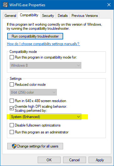
That setting seems to be available in the “Windows Creators update” from springtime last year.
Microsoft also provides some information and tips in that article:
High-DPI Scaling Improvements for Desktop Applications in the Windows 10 Creators Update.
http://winfig.com/wp-content/uploads/2018/02/Scaling_Override.png
2. The interface is too tiny and you want everything to be bigger.
That is probably the case when you have a small 4k screen, for instance a laptop screen, but system wide graphics scaling is at 100% (Panel->Display->Scale and Layout is at 100%).
You can either let the system scale everything up by using the method explained under (1.)
Or you can scale only WinFIG up.
New method:
Go to “Preferences->Other” and enter a value in “Size of the user interface (%)”.
Old method:
By setting a scale factor in an environment variable. Create a text file with a name for instance StartWinFIG.bat and enter the following lines:
set QT_SCALE_FACTOR=2
cd c:\Program Files\WinFIG\
WinFIG.exe
Start WinFIG through running that batch file.
You find more information here: Qt Documentation: High DPI Displays
How can I formats like CGM, EMF or SVG to FIG?
WinFIG does not import any other formats. You can try pstoedit for converting to FIG, but I assume not everything is possible in FIG that is possible in the source format i.e. PostScript.
You find pstoedit here.